MPEG-4 Systems
MPEG doc#: N7504
Date: July 2005
Author: LIM, Young-Kwon (net&tv Inc.)
Introduction
ISO/IEC 14496-1, also known as MPEG-4 Systems, provides the technologies to interactively and synchronously represent and deliver audio-visual contents composed of various objects including audio, visual, 2D/3D vector graphics and etc. It specifies a terminal model for time and buffer management, a framework for the identification, description and logical dependencies of the elementary streams, a packet structure carrying synchronization information and a multiplexed representation of individual elementary streams in a single stream (M4Mux).
System Decoder Model, Timing and Buffer management
Since MPEG-4 Systems shall be capable of working in “push” scenario where the sender transmit the data to the terminal without receiving any signal requesting the data, MPEG-4 Systems defines a conceptual model of the terminal complying with MPEG-4 for the sender to estimate the behavior of the terminal in terms of buffer management and synchronization of data coming from different elementary streams. In this model, two conceptual interfaces are defined to describe the decoder behavior. DAI (DMIF Application Interface) is the interface between the demultiplexer and th decoding buffer, and ESI (Elementary Stream Interface) is the interface between the decoding buffer and decoder. DAI provides series of packets, called SL packets, to the decoding buffer of each elementary stream. SL packet contains one full access unit or the fragment of it as a payload and also carries the timing information of the payload for decoding and composition in a header. Each access unit remains in the decoding buffer before the decoding time arrives and produces a composition unit as a result of decoding which will remain the composition memory until the composition time arrives. By using this conceptual model, sender can guarantee the stream does not break the terminal receiving it by causing overflow or underflow of the decoding buffer or composition.
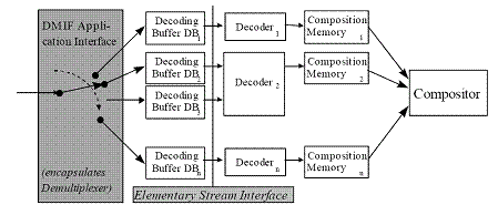
Figure 1. System Decoder Model
Object Description Framework, Method for association
To integrate various audio-visual objects into one presentation, MPEG-4 provides scene description information for spatio-temporal composition of objects and the object description framework to convey information to associate elementary streams to audio-visual objects used in the scene. Each object in the scene requiring association to the elementary stream contains the unique identifier of object descriptor, called object descriptor identifier and object descriptor contains unique identifier of elementary stream, called elementary stream identifier. Object descriptor is a collection of descriptors about elementary streams and each object descriptor can contain more than one descriptors associated to a single object to support scalability of audio-visual objects or capability of choosing one among multiple elementary streams based on user preference such as languages. Elementary stream descriptors include information about the encoding format, configuration information for the decoding process and the sync layer packetization, as well as quality of service requirements for the transmission of the stream and intellectual property identification.
Since scene description and object descriptors are also carried as independent elementary streams, initial object descriptor, a special variant of object descriptor, is designed to be provide the information to access an MPEG-4 presentation. As shown in the Figure 2, initial object descriptor conveys two descriptors about the elementary streams carrying scene description and serious of the object descriptors which are carrying the pointers to each elementary streams.
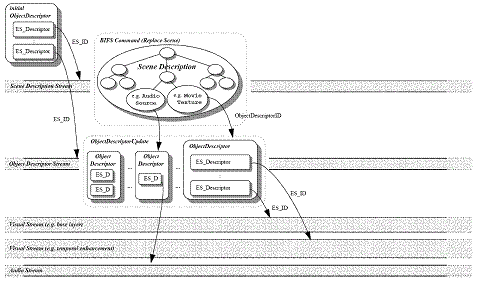
Figure 2. MPEG-4 contents access process
Flexible Synchronization of multiple streams
Synchronization between multiple objects is achieved by two well known concept such as clock reference and time stamps. Clock reference is used to send the time base of receiving terminals by specifying the anticipated value of the clock when the first byte of the packet carrying such information is arrived. Two time stamps can be carried per access unit as explained above, decoding time and composition time. Since each object has different requirements on synchronization and the structure of SL packet can be configured differently per elementary stream, each elementary stream can define its own resolution of timing information and the length of time stamps.
References
[1] ISO/IEC 14496-1, Information technology – coding of audio-visual objects – Part 1: Systems
MPEG4 Mux (M4Mux)
MPEG doc#: N8149
Date: January 2006
1 Introduction
Within the MPEG-4 specification (ISO/IEC 14496), the term delivery layer is used as a generic abstraction of any existing transport protocol stack that may be used to transmit and/or store content complying with ISO/IEC 14496.
The functionality of this layer is not within the scope of ISO/IEC 14496‑1, and only the interface to this layer is considered. Delivery mechanisms serve for transmission as well as storage of streaming data, i.e., a file is considered to be a particular instance of a delivery layer.
For applications where the desired delivery layer does not fully address the needs of a service in terms of delay and overhead, ISO/IEC 14496-1 has defined a simple multiplexing tool (M4Mux) with low delay and low overhead.
2 Flexible Multiplexing
The M4Mux tool is a flexible multiplexer that accommodates interleaving of SL-packetized streams (i.e. data streams packetized according to the synchronization layer defined in 14496-1 and composed of SL Packets) with varying instantaneous bit rate.
The basic data entity of the M4Mux is a M4Mux packet, which has a variable length. One or more SL packets are embedded in a M4Mux packet. The M4Mux tool provides identification of SL packets originating from different elementary streams by means of M4Mux Channel numbers. Each SL-packetized stream is mapped into one M4Mux Channel. M4Mux packets with data from different SL-packetized streams can therefore be arbitrarily interleaved. A sequence of M4Mux packets that are interleaved into one stream is called a M4Mux Stream.
An M4Mux Stream retrieved from storage or transmission may be parsed as a single data stream. However, framing of M4Mux packets by the underlying layer is required for random access or error recovery. There is no requirement to frame each individual M4Mux packet. The M4Mux also requires reliable error detection by the underlying layer. This design has been chosen acknowledging the fact that framing and error detection mechanisms are in many cases provided by the transport protocol stack below the M4Mux.
Two different modes of operation of the M4Mux providing different features and complexity are defined. They are called Simple Mode and MuxCode Mode. An M4Mux Stream may contain an arbitrary mixture of M4Mux packets using either Simple Mode or MuxCode Mode. The syntax and semantics of both modes are specified below.
The delivery timing of the M4Mux Stream can be conveyed by means of M4Mux clock reference time stamps, allowing proper synchronization of the streams carried in the M4Mux stream with the sender clock. The M4Mux stream requires out-of-band configuration prior to usage, for both timing and demultiplexing tables.
Simple Mode
In the simple mode, one SL packet is encapsulated in one M4Mux packet and tagged by an index which is equal to the M4Mux Channel number as indicated in Figure 1. This mode does not require any configuration or maintenance of state by the receiving terminal.

Figure 1 — Structure of M4Mux packet in simple mode
MuxCode mode
In the MuxCode mode, one or more SL packets are encapsulated in one M4Mux packet as indicated in Figure 2. This mode requires configuration and maintenance of state by the receiving terminal. The configuration describes how M4Mux packets are divided into multiple SL packets. In this mode the index value is used to dereference configuration information that defines the allocation of the M4Mux packet payload to different M4Mux Channels.

Figure 2 — Structure of M4Mux packet in MuxCode mode
3 Application areas
The M4Mux tool brings great benefits in applications and services composed of many different streams with low bandwidth and data-rate requirements (such as mete-data or protection streams) and where an efficient transmission is requested in terms of overhead, delays and synchronization.
Application areas include Rich Media delivery over MPEG-2 transport streams or delivery over IP based networks (UDP or RTP).
MPEG-4 Object Content Information
MPEG doc#: N8148
Date: January 2006
Author:
1 Introduction
Object Content Information (OCI) regards meta information about objects. OCI defines a set of descriptors and a stream type that have been defined in MPEG-4 Systems to carry information about the media object in general: OCI descriptors and OCI streams.
2 Technical Solution
The following OCI descriptors are available:
- ContentClassificationDescriptor
- KeyWordDescriptor
- RatingDescriptor
- LanguageDescriptor
- ShortTextualDescriptor
- ExpandedTextualDescriptor
- ContentCreatorNameDescriptor
- ContentCreationDateDescriptor
- OCICreatorNameDescriptor
- OCICreationDateDescriptor
- SmpteCameraPositionDescriptor
- SegmentDescriptor
- MediaTimeDescriptor
Content is classified, for example, by genre. Classification schemata need to be registered with a registration authority to make sure that all implementers of MPEG-4 systems have access to this information. The same approach holds for the rating descriptor that is supposed to indicate the suitability of the content for different groups of audiences. Descriptors for keywords, short text, and expanded text are all freestyle but presumably in increasing order of complexity. Name of content creators and OCI creators as well as the creation dates for those are self-explanatory. The camera position descriptor inherited from SMPTE allows keeping track of the camera position for that media stream. Finally, the segment descriptor and media time descriptors are additions that allow assigning a name to a temporal segment of the media stream based on the definition of a media timeline (see section on synchronization).
Any of those descriptors can be attached to an Object Descriptor (OD). This means that all the ESs referenced through this OD share the same (static) object content information. The only information that can be attributed to a single stream within one single OD is the language, because it should be possible to convey different language variants of the same content as one logical media object. OCI also may be dynamically changing over time—for example, the keywords and textual descriptor. In that case, a separate OCI stream may be used to convey that information. Each OD can refer to one OCI stream at most. Within an OCI stream, an OCI_Event message is used to wrap each set of descriptors that is to be conveyed jointly. The OCI_Event has the added functionality that the embedded set of OCI descriptors can now be associated with a temporal segment of the media stream, identified through start time and duration. The SmpteCameraPositionDescriptor is a typical example of a descriptor that mostly makes sense when conveyed in an OCI stream, as it may be assumed that camera position changes frequently over time.
3 Application areas
OCI is a metadata format that does not address any specific application rather but it is rather generic in nature. It should be mentioned that OCI was established at a time when no other MPEG metadata format was available. Today there is also the MPEG-7 multimedia description framework. All concepts expressed in OCI can equally well be expressed in MPEG-7. In fact, a label for MPEG-7 streams has already been reserved. So, instead of an OCI stream, an MPEG-7 stream can be associated with an MPEG-4 media stream. It is hard to predict how OCI and MPEG-7 will coexist. It is conceivable that future MPEG-4 applications will rely more on MPEG-7 than on MPEG-4 OCI as a metadata format because of its larger capabilities, but it may also be that applications with few metadata requirements continue to use OCI.
MPEG-4 Terminal Architecture
MPEG doc#: N7610
October 2005
Authors: Jean Le Feuvre, Cyril Concolato
Introduction
Complex, interactive multimedia computing is a very broad subject: support for numerous coding formats for natural audio and video, fundamental differences in user interface (2D internet portals, 3D gaming), in delivery networks (cable/satellite broadcasts, broadband internet or mobile networks) and in terminals (PC, set-top boxes, PDAs/Mobile Phones) have increased the multimedia market segmentation. This is where MPEG-4 comes into the big picture. The MPEG-4 standard (ISO/IEC 14496), officially entitled “Coding of audio-visual objects”, is a unified multimedia framework, featuring a wide range of coding techniques for natural audio and video, 2D and 3D graphics, complex synthetic objects such as 3D meshes and avatars or computer-generated music. But the unique strength of this standard lies in its underlying system architecture, powerful yet flexible enough to cover all needs of modern multimedia, from simple audio-video content to complex 3D worlds.
MPEG-4 Terminal Architecture
MPEG-4 data is carried by elementary streams, or logical transportation channels, and a stream can only carry a given type of data (scene data, visual data, etc…). An audio-visual object is composed of one or several of these streams, allowing scalable representations, alternate coding (bitrate, resolution, language…), enhanced with timed metadata (MPEG-7) and protection information. An object is described by an ObjectDescriptor, giving simple meta-data related to the object (ObjectContentInformation) such as content creation information or chapter time layout. This descriptor also contains all information related to stream setup, including synchronization information or initialization data for decoders. MPEG-4 objects are not static; they can be modified during the course of the presentation, in order to fine-tune the media data to network and client capabilities.
The scene description (BIFS, LASeR) is then used to place each object, with potentially various effects applied to it, on the display, and to determined how user interactions (pointing devices, keyboards, remote controllers) modify the content. As with all other objects, scene description data is carried in elementary streams, allowing dynamic control of the presentation at the server side.
The MPEG-4 terminal can be divided in four logical blocks:
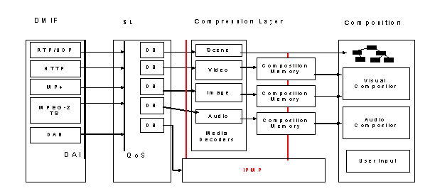
DMIF (Delivery Multimedia Integration Framework), where all communications and data transfer between the data source and the terminal are abstracted through a logical API called the DAI (DMIF Application Interface), regardless of the network type (broadcast or interactive), allowing easy integration of existing protocols inside the terminal. This layer is in charge of extracting the logical elementary stream from the physical input stream whenever needed, through demultiplexing (MPEG-2, M4Mux) or de-aggregation (MPEG-4 over RTP). This layer also provides the initial setup information for the presentation (usually the scene elementary stream information). It shall be noticed that most audio-video formats can be wrapped through DMIF, for example by using a default scene description, enabling support for many existing contents, such as internet movie files (MPEG1, AVI, RealMedia, QuickTime) or internet radios (IceCast and ShoutCast), at no cost for the terminal.
The SL (Synchronization Layer), where data packets are received with their timing, packetization and other various information. Data packets are re-assembled into MPEG-4 Access Units, the base media unit understandable by the decoders, and streams synchronization is performed against the associated stream timeline. Note that several timelines may exist in a presentation, allowing media navigation (seeking, fast forward) from inside the content. The SL information can be configured in the elementary stream’s description, based on media or network constraints. This information can be transported physically (“bits on the wire”) or logically, extracted from other information carried by the underlying protocol (as for example in the transport of MPEG-4 streams on RTP). In a typical implementation, network QoS (Quality of Service) as well as decoding buffer (DB) management is performed at this stage.
The Compression Layer where all media decoding is performed. This may imply a decryption process between the decoding buffer and the decoder, as well as an encryption or watermarking process after the decoder, performed by MPEG-4 IPMP modules. One part of the terminal resource usage is estimated at this level for QoS management purposes. Note that this layer is the only place in the MPEG-4 terminal aware of the coding format, thus allowing addition of new coding standards in a very efficient way. For example, changing the MPEG-4 BIFS representation to the new LASeR representation doesn’t impact the terminal synchronization architecture in any way, although these two representations are completely different.
The Composition layer, performing the final layout of the objects. This stage is usually divided in two entities: the visual compositor, in charge of drawing 2D and 3D objects on screen, and the audio compositor responsible of audio objects positioning and mixing. The second main part of terminal resource usage is estimated here. The presentation engine is also managing user interactions, such as pointing device and keyboard inputs.
Advantages and Applications
The modularity of the network and synchronization layer enables hybrids delivery scenario, such as a mix of broadcast and on-demand streaming with possible back channels, typically suited for interactive television. The reliable synchronization of streams regardless of their origins along with stream-based quality of service management will help content providers guarantee their users a pleasant experience.
The modularity of the coding tools, expressed as MPEG well-known profiles and levels, allows for easy customization of the terminal for a dedicated marked segment (for example, music and cover art hardware players), reducing deployment costs while ensuring compatibility with full-featured MPEG-4 terminals, a key feature of modern multimedia, especially in the domain of media home gateways.
The dynamic and incremental construction of the scene description, a unique feature in MPEG-4, enhances the media experience by releasing the terminal of many of the operations needed by script-based scene descriptions languages. Coupled with MPEG-4 timing model, this guarantees a similar behavior of the content on all terminals.
Typical applications include interactive broadcast TV services (betting, shopping, sport statistics…), entertainment content (enhanced DVD, simple edutainment), corporate training, 2-Dimensional and 3-Dimensional multimedia portals. The addition of ECMAScript and MPEG-J technologies opens an almost limitless field of application of the MPEG-4 standard.
References
[1] ISO/IEC 14496-1, Coding of audio-visual objects, Part 1: Systems.
[2] ISO/IEC 14496-11, Coding of audio-visual objects, Part 11: Delivery Multimedia Integration Framework.
[3] ISO/IEC 14496-6, Coding of audio-visual objects, Part 6: Scene description and Application engine (BIFS, XMT, MPEG-J).
[4] ISO/IEC 14496-20, Coding of audio-visual objects, Part 20: Lightweight Scene Representation (LASeR).
[5] ISO/IEC 14496-13, Coding of audio-visual objects, Part 13: Intellectual Property Management Protection (IPMP) extensions.
[6] ISO/IEC 16262, ECMAScript language specification.