MPEG-1 Audio
MPEG doc#: N7703
Date: October 2005
Authors: B. Grill, S. Quackenbush
MPEG-1 Layer I or II Audio is a generic subband coder operating at bit rates in the range of 32 to 448 kb/s and supporting sampling frequencies of 32, 44.1 and 48 kHz. Typical bit rates for Layer II are in the range of 128-256 kbit/s, and 384 kb/s for professional applications.
MPEG-1 Layers I and II (MP1 or MP2) are perceptual audio coders for 1- or 2-channel audio content. Layer I has been designed for applications that require both low complexity decoding and encoding. Layer II provides for a higher compression efficiency for a slightly higher complexity. Using MPEG-1 Layer I one can compress high quality audio CD data at a typical bitrate of 384 kb/s while maintaining a high audio quality after decoding. Layer II requires bit rates in the range of 192 to 256 kb/s for near CD quality. A Layer II decoder can also decode Layer I bitstreams.
MPEG-1 Layer 3 (or MP3) is a 1- or 2-channel perceptual audio coder that provides excellent compression of music signals. Compared to Layer 1 and Layer 2 it provides a higher compression efficiency. It can typically compress high quality audio CD data by a factor of 12 while maintaining a high audio quality. In general MP3 is appropriate for applications involving storage or transmission of mono or stereo music or other audio signals. Since it is implemented on virtually all digital audio devices playback is always ensured
Thanks to its low complexity decoding combined with high robustness against cascaded encoding/decoding and transmission errors, MPEG-1 Layer II is used in digital audio and video broadcast applications (DVB and DAB). It is also used in Video CD, as well as in a variety of studio applications.
Layer 3, or as it is mostly called nowadays ”mp3”, is the most pervasive audio coding format for storage of music on PC platforms, and transmission of music over the Internet. Mp3 has created a new class of consumer electronics devices named after it, the mp3 player. It is found on almost all CD and DVD players and in an increasing number of car stereo systems.and new innovative home stereo devices like networked home music servers. Additionally, Layer 3 finds wide application in satellite digital audio broadcast and on cellular phones.
MPEG-1 Layer 3 was standardized for the higher sampling rates of 32, 44.1 and 48 kHz in MPEG-1 in 1992..
Figure 1 shows a high level overview of the MPEG-1 Layers I and II coders. The input signal is transformed into 32 subband signals that are uniformly distributed over frequency by means of a critically sampled QMF filterbank. The critically down sampled subband signals are grouped in a so called allocation frame (384 and 1152 subband samples for Layer I and II respectively). By means of Adaptive PCM, these allocation frames are subsequently quantized and coded into an MPEG-1 bitstream. At the decoder side, the bitstream is decoded into the subband samples which are subsequently fed into the inverse QMF filterbank.
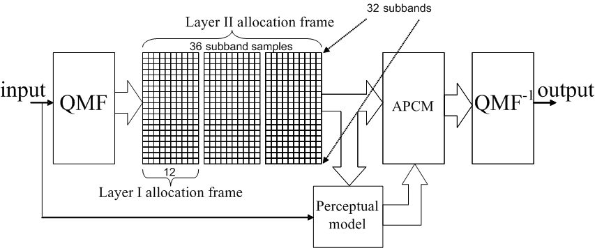
Figure 1 – High level overview of MPEG-1 Layers I and II coder
Next to coding of mono and independent coding of stereo signals, also joint coding of stereo signals is supported by applying a technology called intensity stereo coding. Intensity coding exploits the property of the human auditory system that at high frequencies the perceived stereo image depends on intensity level differences.
A block diagram of the Layer 3 encoder algorithm is show in the following diagram:
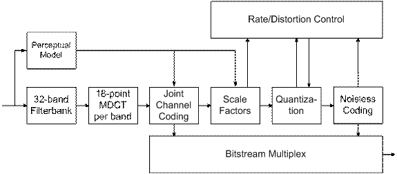
These blocks are described below.
Filter bank
The filter bank used in MPEG Layer-3 is a hybrid filter bank which consists of a polyphase filter bank and a Modified Discrete Cosine Transform (MDCT). This hybrid form was chosen for reasons of providing the same frame sizes as in Layer-1 and Layer-2.
Perceptual Model
The perceptual model mainly determines the quality of a given encoder implementation. It uses either a separate filter bank or combines the calculation of energy values (for the masking calculations) and the main filter bank. The output of the perceptual model consists of values for the masking threshold or the allowed noise for each coder partition. If the quantization noise can be kept below the masking threshold, then the compression results should be indistinguishable from the original signal.
Joint Stereo
Joint stereo coding takes advantage of the fact that both channels of a stereo channel pair contain far the same information. These stereophonic irrelevancies and redundancies are exploited to reduce the total bitrate. Joint stereo is used in cases where only low bitrates are available but stereo signals are desired.
Quantization and Coding
A system of two nested iteration loops is the common solution for quantization and coding in a Layer-3 encoder.
Quantization is done via a power-law quantizer. In this way, larger values are automatically coded with less accuracy and some noise shaping is already built into the quantization process.
The quantized values are coded by Huffman coding. As a specific method for entropy coding, Huffman coding is lossless. This is called noiseless coding because no noise is added to the audio signal.
The process to find the optimum gain and scalefactors for a given block, bit-rate and output from the perceptual model is usually done by two nested iteration loops in an analysis-by-synthesis way:
Inner iteration loop (rate loop)
The Huffman code tables assign shorter code words to (more frequent) smaller quantized values. If the number of bits resulting from the coding operation exceeds the number of bits available to code a given block of data, this can be corrected by adjusting the global gain to result in a larger quantization step size, leading to smaller quantized values. This operation is repeated with different quantization step sizes until the resulting bit demand for Huffman coding is small enough. The loop is called rate loop because it modifies the overall coder rate until it is small enough.
Outer iteration loop (noise control/distortion loop)
To shape the quantization noise according to the masking threshold, scalefactors are applied to each scalefactor band. The systems starts with a default factor of 1.0 for each band. If the quantization noise in a given band is found to exceed the masking threshold (allowed noise) as supplied by the perceptual model, the scalefactor for this band is adjusted to reduce the quantization noise. Since achieving a smaller quantization noise requires a larger number of quantization steps and thus a higher bitrate, the rate adjustment loop has to be repeated every time new scalefactors are used. In other words, the rate loop is nested within the noise control loop. The outer (noise control) loop is executed until the actual noise (computed from the difference of the original spectral values minus the quantized spectral values) is below the masking threshold for every scalefactor band (i.e. critical band).