MPEG-2 Systems
Terminal architecture
MPEG doc#: N7679
Date: October 2005
Author: Peter Schirling
Introduction
MPEG-1 [1] and MPEG-2 [2] are unique points in history for digital media as each represents a first of a kind. This brief paper will describe MPEG-1 Systems. The description of MPEG-2 Systems is provided in a separate brief.
The systems layers of each of these international standards are also unique in many ways. What they have in common is that the systems layer provides the information about the audio and video layers with stream identification and synchronization information essential to the decoding and subsequent rendering for each of them. The audio and video are bounded while the systems layer is viewed as an unbounded element and can, therefore, be a very complex environment. The systems layer is required to carry not only the multiplexed audio and video information but all of the other non-audio/video information, and in many cases private, data needed for a successful and pleasing user experience.
Background: application interoperability
When MPEG-1 video and audio were being developed it was recognized that if they were going to be rendered synchronously there needed to be a means to accomplish that. This problem had never been tackled before because audio and video in the compressed digital domain had never existed together before. As you will see below in the brief description of the MPEG Systems layer design the solution is a unique multiplex designed to precisely deliver a clock reference and elementary streams in such a way as to enable audio‑video synchronization.
MPEG-1 is intended for use in relatively error free environment of CD’s or optical discs.
MPEG Systems design
The design principal behind both MPEG-1 Systems is based on an on-time, error free delivery of a stream of bytes. The time interval (bit rate) between a byte leaving the transmitter is the same as the time interval at its arrival at the receiver. By maintaining this constant delay it is possible to imbed a clock in the byte stream that can be used by the receiver to control a clock reference in the receiver. This clock can then be used to pace the decoding of the audio-video information keeping them in sync. As a part of this timing model all audio and video samples are intended to be presented once unless specified otherwise.
Unlike today’s Internet environment where audio and video can be delivered separately using different sockets, the optical disc environment is defined to use a single stream (in-band) of information (bytes) over which both audio and video (and all other information) are delivered. Further constraints are present because optical disks (CD or DVD) are constant speed devices while audio or video information may be variable rate.
The MPEG-1 SYSMUX, as it is called contains bitrate information in order to restore the bitrate intended when the content was encoded (compressed).
The most important innovation introduced by MPEG-1 and carried over and extended into MPEG-2 Systems is the specification of a System Target Decoder (STD) model. The STD is an idealized model of a demultiplexing and decoding complex that precisely specifies the delivery time of each byte in an MPEG Systems multiplex and its distribution to the appropriate decoder or resource in the complex.
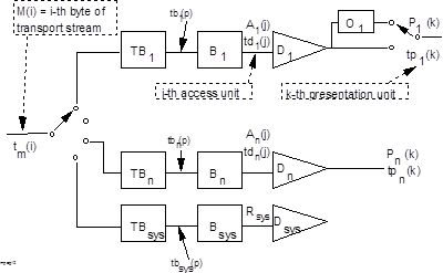
Figure 1 - MPEG-2 System Target Decoder
MPEG-2 supports two methods of multiplexing. MPEG-2 Program Stream (PS) is based on the needs and characteristics of optical storage devices though it is not limited to such use and is the backward compatible successor to MPEG-1 SYSMUX. The typical terminal architecture is shown in Figure 2 below. The MPEG-2 Transport Stream design was established to satisfy the needs associated with broadcasting over terrestrial networks as well as satellite and cable networks and it’s typical terminal architecture is shown in figure 3 below. While MPEG only specifies the demultiplexing and decoding behavior, along with stream syntax, it is essential that implementers understand how these are an integral part of a terminal or device that can render both the audio and video once they are decompressed. It is also important to understand what the input to a receiver complex consists of. Figure 2 below illustrates the scope of MPEG-2 Systems as a terminal architecture. The input to a Program Stream demultiplexor is a byte stream retrieved from the media in the player from which all non-MPEG stream information has been removed so the MPEG demultiplexor is only presented with a compliant MPEG-2 Program Stream. If a PACK HEADER is detected the bitrate field is used to establish the assigned bitrate.
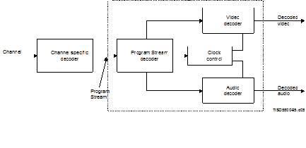
Figure 2 - MPEG-2 Prototypical program demultiplexing and decoding terminal
![]()
Figure 3 - Prototypical transport demultiplexing and decoding terminal
The Transport Stream demultiplexor is also a byte stream derived from an RF decoder. The RF decoder removes any forward error correction information after applying it if necessary and pushes the data to the system decoder which proceeds to separate the audio, video, and systems information and sends it to the appropriate element in the complex for processing.
Likewise, the decoded (decompressed) audio and video data are sent on for rendering into pictures and sound. If the media has been authored correctly and the data retrieval does not produce uncorrectable data errors and the decoding complex is operating correctly, the video and audio will play in sync and with the sound and picture quality at that processed when it was compressed.
MPEG-1 SYSMUX (and MPEG-2 Program Stream) can only transport a single Program. A Program is define as all information (audio, video, data etc) having a common clock reference. Each Program, however, is capable of multiple audio and video elementary streams.
Target applications
MPEG-2 - Standard Definition and High Definition television broadcasting over Terrestrial, satellite and cable networks, and optical disk - specifically DVD for movie distribution.
References
[1] ISO/IEC 11172-1 Coding of moving pictures and associated audio for digital storage media at up to about 1,5 Mbit/s: Part 1 Systems
[2] ITU-T Rec. H.222.0 | ISO/IEC 13818-1:2000 Generic coding of moving pictures and associated audio information, Part 1: Systems
Multiplexing and Synchronisation
MPEG doc#: N7680
Date: October 2005
Author: Peter Schirling
Introduction
MPEG-1 [1] and MPEG-2 [2] are unique points in history for digital media as each represents a first of a kind. This brief paper will describe MPEG-1 Systems. The description of MPEG-1 Systems is provided in a separate brief.
The systems layers of each of these international standards are also unique in many ways. What they have in common is that the systems layer provides the information about the audio and video layers with stream identification and synchronization information essential to the decoding and subsequent rendering for each of them. The audio and video are bounded while the systems layer is viewed as an unbounded element and can, therefore, be a very complex environment. The systems layer is required to carry not only the multiplexed audio and video information but all of the other non-audio/video information, and in many cases private, data needed for a successful and pleasing user experience.
Background: application interoperability
When MPEG-1 video and audio were being developed it was recognized that if they were going to be rendered synchronously there needed to be a means to accomplish that. This was also true of the MPEG-2 CODECS. This problem was solved in MPEG-1 Systems for storage media such as video CD and extended in MPEG-2 Systems to accommodate broadcasting of MPEG audio and video and high capacity sotrgae devices such as DVD. As you will see below in the brief description of the MPEG Systems layer design the solution is a unique multiplex designed to precisely deliver a clock reference as well as the elementary streams in such a way as to enable audio‑video synchronization. The MPEG-1 and MPEG-2 CODECS differ in many ways and so too does the systems layer for MPEG-1 and MPEG-2 that support the delivery of audio, video, and other information because the target applications differ as well.
The MPEG-2 standard is directed at broadcasting of high quality images and audio over satellite, cable or terrestrial networks. Each is prone to errors caused by different factors associated with the delivery environments. The MPEG Systems Committee had to solve these problems and ensure that there is complete interoperability amongst the various environments as well as backward compatibility with MPEG-1 Systems.
MPEG Systems design
The design principal behind both MPEG-1 and MPEG-2 Systems is based on an on-time, error free delivery of a stream of bytes. The time interval (bit rate) between a byte leaving the transmitter is the same as the time interval at its arrival at the receiver. By maintaining this constant delay it is possible to imbed an encoder clock reference in the byte stream that can be used by the receiver to control a clock reference in the demultiplexor/decoder complex. This clock reference is used to pace the decoding of the audio-video information thus keeping them in sync. As a part of this timing model all audio and video samples are intended to be presented once unless specified otherwise.
Unlike today’s Internet environment where audio and video can be delivered separately using different sockets, both the optical disc and broadcast environments are defined to use a single stream (in-band) of information (bytes) over which both audio and video (and all other information) are delivered. Further constraints are present because optical disks (CD or DVD) are constant speed devices while audio or video information may be variable rate.
Therefore, MPEG-2 Program Stream contains bitrate information in order to restore the bitrate intended when the content was encoded and is backward compatible with the MPEG-1 SYSMUX. MPEG-2 Transport Stream, on the other hand, does not contain these values because the bitrate of the stream is established at demultiplexor and extracting a value becomes unnecessary. Other differences between MPEG-1 and MPEG-2 are highlighted below.
The most important innovation introduced by MPEG-1 and carried over and extended into MPEG-2 Systems is the specification of a System Target Decoder (STD) model. The STD is an idealized model of a demultiplexing and decoding complex that precisely specifies the delivery time of each byte in an MPEG Systems multiplex and its distribution to the appropriate decoder or resource in the complex.
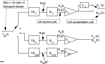
Figure 1 - MPEG-2 System Target Decoder
The STD is a buffer model and is normative. Thus it is used by implementers to verify that their implementation of the normative elements of the standard function correctly. The syntax of stream decoding is the other element that needs to be verified for correctness using the text of the standard. The clock recovery and buffer management are critical to the proper operation of a demultiplexing and decoding complex. The consequences of improper clock are recovery manifest themselves in noticeable audio and video faults such as sound glitches and picture artifacts or frozen frames. The causes of flawed or failed clock recovery are many and varied. The net is that audio and video decode run too fast or too slow and both sync and quality are effected because the buffers that hold the compressed data stream either empty (too fast a pace) or overflow (too slow pacing).
SYNCHRONIZATION
The figure (2) below shows a prototypical end-to-end system that compresses separate audio and video streams and then multiplexes them into an MPEG-2 Program Stream or Transport Stream. A critical task that is performed when encoding a stream is the sampling and insertion of a clock reference carried with the elementary streams and a system clock reference (PCR) for the multiplex carried in the pack header (PS) or Transport Header (TS). The system time clock used in the encoding stage is a very stable and accurate 127MHz clock. It produces clock values or time stamps associated with the access units of the elementary streams (audio and video). This PTS (Presentation Timestamp), as it is called, is a reference clock value inserted at encode time into the PES (Packetized Elementary Stream) headers of the data stream at intervals not to exceed 700ms (normative requirement). The sample rates for audio compression differ from video compression so the values associated with the PTS are not the same, but that does not matter nor is it necessary. The clock values carried with the A-V data are only used for comparison with a value of the system time clock (PCR) as the means of assuring A-V Sync. If the decoder clock reference (STC) drifts then a phase lock loop with alter its frequency to bring it back in sync with the encoder clock rate. This is the way the clock in the decoding complex keeps exactly the same clock rate as the system clock used in the encoding complex that prepared the stream. Doing so allows the PTS values carried with the audio-video data to be used to compare with the decoder’s system clock reference. If the PTS values become separated in time too far that means that the pace of decoding is faster or slower than intended. That is corrected by either dropping or freezing (repeating) a frame of audio or video in order to bring them both back into sync. It is a simple but elegant means of having an end-to-end clock in a network in which one is not inherently present unlike the internet.
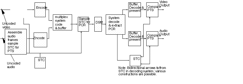
Figure 2 - Prototypical complex illustrating how synchronization is achieved
MPEG-2 Program Stream can only carry a single Program but MPEG-2 Transport Streams can support multiple programs. A Program is define as all information (audio, video, data etc) having a common clock reference. A Transport Stream can carry multiple Program Clock References (PCR). Each Program, however, is capable of multiple audio and video elementary streams.
MULTIPLEXING
An MPEG-2 Program Stream or Transport Stream is a single in-band stream of bytes that contains all of the audio, video, and other information needed in order to decode and then render the content in simultaneously and in sync. This is accomplished by multiplexing the compressed data in such a way as to ensure that the bitrate of the audio and video elementary streams is properly maintained at the input to the decoders for each. The maximum bitrate for audio and video are specified depending on the profile that is used. However the maximum bitrate for a Transport Stream multiplex is only limited by the network bandwidth. Likewise the maximum bitrate of a Program Stream multiplex is limited by data rate that a storage device can sustain. If Program Stream is used on a storage device the audio and video bitrates are also limited to the data rate of the device rather than the maximum rate permitted by the profile. While Program Stream and Transport Stream are not limited to being used as illustrated here they are designed for such use.
Target applications
MPEG-2 - Standard Definition and High Definition television broadcasting over Terrestrial, satellite and cable networks, and optical disk - specifically DVD for movie distribution.
References
[1] ISO/IEC 11172-1 Coding of moving pictures and associated audio for digital storage media at up to about 1,5 Mbit/s: Part 1 Systems
[2] ITU-T Rec. H.222.0 | ISO/IEC 13818-1:2000 Generic coding of moving pictures and associated audio information, Part 1: Systems